Craft 2-Wheeler Extended is a simulator for 2-wheel vehicles. This animation tool makes it easy for the user to create realistic simulations for vehicles in motion. The vehicle is controlled with an input device directly through 3ds Max or Maya. The user links the model that will be rendered to Craft 2-Wheeler Extended for it to inherit its movement. Steering, braking, boosting, skidding, etc. is performed in real-time with a DirectX input device, keyboard or 3dxmouse. All Craft 2-Wheeler Extended parameters can be altered in real time and may create some very peculiar motorcycle shape changes during recording.
The surface on which Craft 2-Wheeler Extended drives can take any shape, be upside down or twist oddly. Surfaces can even be animated during recording with Craft 2-Wheeler Extended.
|
Select the Craft 2-Wheeler Extended in the tool tree list and click on the Input settings button in the tool bar. This will open the input settings window for Craft 2-Wheeler Extended. 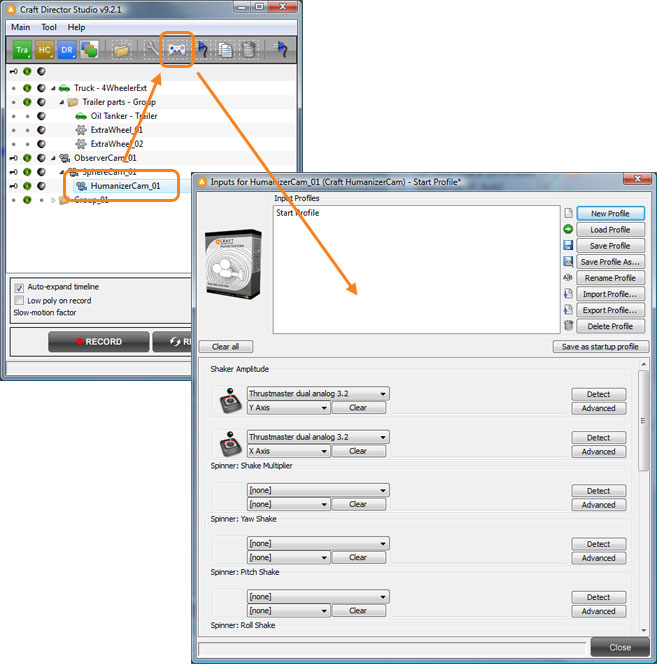


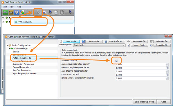
When Autonomous mode has been activated, Craft 2-Wheeler Extended will pursue 2WheelerExt_01_TargetMesh. This, for example, enables Craft 2-Wheeler Extended to follow a spline.
Directions for Craft 2-Wheeler Extended to follow a track (spline):


By using the chassis relocator (see illustration, 2WheelerExt_01_ChassisRelocatorMesh), the animation can be fine-tuned after the recording has taken place. The chassis relocator can be keyframed according to specific needs.
Maneuver example:
Accelerates the vehicle forward or backward.
Turns the vehicle right or left. 
Gives the vehicles a boost in velocity.
The vehicle will brake as much as possible without locking the wheels until it comes to a stop.
Used to control the vehicle’s skid. The vehicle’s rear wheel lose traction.
Locks the wheels and brakes the vehicle until it comes to a stop.
Simulates driving on gravel.
The rear wheel spin to create a burnout.
Spinners enables the change of parameter values with an input controller in real-time.
Re-Initialize Bike Attributes
This button enables re-initialization of the bike’s physical attributes.
Hide Helpers
Hides the Helpers.
Hide Helpers During Recording
Hides the Helpers during recording.
Hide Follow Camera
Hides the Follow Camera.
Hide Driver Camera
Hides the Driver Camera.
Hide TopView Camera
Hides TopView Camera.
Enable Seamless Transitions
Enable Seamless Transitions requires more memory usage.
Autonomous mode follow strength
This factor decides how tightly the bike follows the target.
Follow Strength Response Factor
This value determines how much of the bike’s speed is used to follow the target. E.g. if the value is 1, 100% of the bike’s speed is used.
Auto-Steering Response factor
This value determines how much of the bike’s steering is used in order to steer towards the target. E.g. if the value is 0.3, 30% of the bike’s steering is used.
Ignore Sphere Radius (length relative)
This sets a virtual sphere about front of the bike which is the distance at which the bike will begin to react to the TargetMesh. I.e. the TargetMesh must be outside this sphere to move the bike. The radius is multiplied by the length of the bike to be relative.
Maximum Steering Change Velocity
How fast the wheels can turn in rads per sec.
Speed dependent Turn Radius Reduction Factor
By this factor the turn radius will be decreased linearly with the bike velocity.
Turn Base (Back Wheel Relative)
If larger than 0 the bike will turn with both wheels.
Fixate Wheel Bottom Nodes
When checked the WheelBottomMesh will not turn with the wheel yaw.
Front Stiffness
The Stiffness determines how much force the springs have.
Front Damping
The Damping determines how dull the dampers are.
Back Stiffness
The Stiffness determines how much force the springs have.
Back Damping
The Damping determines how dull the dampers are.
Booster Stiffness Multiplier
Increases the Stiffness by this factor times the booster value.
Mass Multiplier
Mass Multiplier. A greater value = a heavier vehicle.
Surface Edge Response Factor
Can be used as a wheel air pressure parameter. It softens the transition for the wheels when moving from one polygon face to another but may cause instability when too low.
Suspension Length (Radius Relative)
The Suspension Length (Radius Relative).
Maximum Spring Velocity (Radius Rel)
The maximum bike body relative wheel velocity (times the radius).
Minimum Ground Distance (Chassis Relative)
The minimum distance the bottom of the bike chassis can have relative its initial height.
Maximum Forward Tilt Angle
The maximum angle the bike body can have in the forward direction.
Maximum Side Tilt Angle
The maximum angle the bike body can have sideways.
Gravity
Gravity.
Relative Max Jump Velocity
Scale relative maximum velocity during jumping.
Jump Anti-Tumbling Regulator
Automatically orients the bike to a horizontal orientation during a jump.
Landing Neutralizer
Can in some cases improve the landings after a jump.
Landing Skidding Factor
How large the friction of the ground is after the bike has landed.
Skidding Offset Value
This value is added to the input device value for ‘Skidding’ as an offset.
Skidding Release Value (Lateral Vel Rel)
When the bike reaches this sideway velocity during a turn the bike will automatically generate a ‘Skidding’ input device signal.
Skidding Release Response Factor
Determines how fast the bike will stop skidding.
Gravel Shake Offset Value
This value is added to the input device value for ‘Gravel Shake Amplitude’ as an offset.
Gravel Roughness
How rough the gravel shake is.
External Force Offset Value
This value is added to the input device value for ‘External Force’ as an offset.
Skid Brake Stop Factor
Determines how fast the bike should come to a stop when the skid brake is released.
Skidding Release Response Factor
Determines how fast the bike will stop skidding.
Burnout Shake
How much the bike should shake during a burnout.
Burnout Tilting Force
How much the bike chassis should be tilted during a burnout.
Burnout Fadeout Factor
How fast the burnout dies out.
Ray Multiplier
Increasing the ray multiplier will increase accuracy but will increase the computation time.
Degrees Per Ray
How many degrees will be added for each extra ray forward and backwards, seen from the center of the wheel straight down. However, the maximum degree a ray is cast is 85 degrees.
Gas Pedal (Forw/Backw) Response Factor
How fast the vehicle accelerates and decelerates.
Gas Pedal (Forw/Backw) Maximum
Maximum velocity of the vehicle.
Steering Wheel (Right/Left) Response Factor
How fast the vehicle will turn.
Steering Wheel (Right/Left) Maximum
The turn radius of the vehicle.
Booster Response Factor
How fast the vehicle accelerates when using the booster.
Booster Maximum
Maximum velocity when using the booster (value is multiplied with Gas Pedal Maximum).
ABS Brake Response Factor
How fast the vehicle will brake (is not used).
ABS Brake Maximum
How hard the vehicle will brake.
Skidding Response Factor
Response time for the vehicle to begin skidding.
Skidding Maximum
The maximum value for a skid.
Skid Brake Response Factor
Affects how much friction the vehicle has during the time the Skid brake button is used.
Skid Brake Maximum
Not used.
Gravel Shake Amplitude Response Factor
The response time for the Gravel Shake.
Gravel Shake Amplitude Maximum
Determines how hard the vehicle will shake.
Burnout Response Factor
Determines how fast the back wheel will accelerate during a burnout.
Burnout Maximum
Maximum velocity for the back wheel during a burnout.
External Force Response Factor
This value determines how fast Craft 2-Wheeler Extended will respond to the External Force.
External Force Maximum
This value determines how much force is applied by the External Force.
 Optimizing the scene